

Description
Application Scenarios
A compressor OEM was packaging a two-stage centrifugal air compressor for an onshore gas-processing facility. The end user’s protection philosophy called for a single calibrated thrust-position signal per compressor that could drive both a warning alarm and a shutdown decision in the existing DCS — but there was no cabinet space, budget or maintenance headcount for a dedicated API 670 monitoring rack, and the plant did not want another proprietary software interface to support. The engineering team selected the 991-10-XX-02-00 MOD 163930-01 because the Proximitor excitation and conditioning electronics live inside the transmitter housing, eliminating the separate driver enclosure, rack slot and interconnecting coaxial cable. They mounted the unit to the compressor local control panel with the supplied bulkhead screws, specified one 5.0 m and one 7.0 m transducer system length for two different skid layouts, and delivered one thrust signal per machine with no additional marshalling hardware.
The value only became visible during commissioning. A startup surge pushed one rotor toward the thrust bearing, and the 4–20 mA output tracked cleanly past the pre-set warning level while the buffered gap-voltage waveform on the PROX OUT connector showed a smooth DC shift rather than a noisy or clipped signal. The DCS raised the alarm, the operators relaxed the balance-piston pressure, and the trend returned to centre. Months later, when a cable pull disturbed a probe connection, the transmitter did not hold a plausible value and silently feed it to the control system — it drove the loop below 3.6 mA within 100 microseconds, so the fault was logged as a sensor problem rather than a mechanical event. That distinction is exactly what makes axial-position monitoring defensible in a safety and maintenance review.
Parameter
| Main Parameters | Value / Description |
|---|---|
| Product Model | 991-10-XX-02-00 (MOD 163930-01) |
| Manufacturer | Bently Nevada (Baker Hughes), USA |
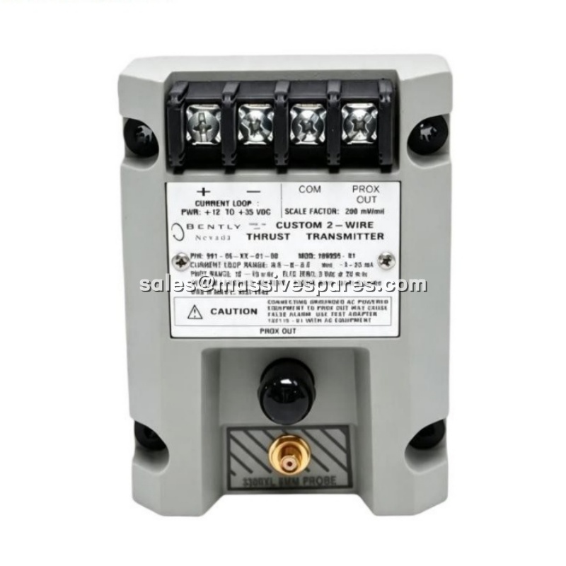
| Product Category | Two-wire, loop-powered thrust / axial shaft position transmitter with integrated Proximitor |
| Ordering Code Structure | 991-AA-BB-CC-DD — AA full-scale, BB system length, CC mounting, DD agency approval |
| Full-Scale Option (AA = -10) | 0–10 mils unidirectional axial position (verify scaling against the original order code) |
| Transducer Input | One non-contacting 3300 NSv proximity probe with matching 75 Ω extension cable |
| Output Signal | 4–20 mA DC, proportional to axial displacement, 2-wire loop-powered configuration |
| Supply Voltage | +12 to +35 V DC at the transmitter terminals |
| Loop Accuracy | Within ±1.5 % of full-scale range, typical (measured from TEST input to voltage across a 250 Ω loop resistance) |
| Maximum Loop Resistance | 1,000 Ω including cable, at 35 V DC |
| Current Limiting | 23 mA typical |
| Mounting Option (CC = -02) | Bulkhead screw mounting, four 6-32 mounting holes |
| Agency Approval (DD = -00) | None selected; general-purpose, non-hazardous location |
| PROX OUT Linear Range | 0.25 to 1.65 mm (10 to 65 mils) |
| PROX OUT Scale Factor | 7.87 mV/μm (200 mV/mil), ±6.5 % typical including interchangeability error |
| PROX OUT Output Impedance | 10 kΩ, calibrated for a 10 MΩ load |
| Minimum Target Size | 9.5 mm (0.375 in) diameter |
| Not OK / Signal Defeat Response | Output below 3.6 mA within 100 µs; restored within 0.1 s after the condition clears |
| Zero & Span Adjustment | Non-interacting external potentiometers beneath the transmitter label |
| Measurement Target | AISI 4140 steel (reference target material in the datasheet) |
| Operating Temperature | Transmitter −35 °C to +85 °C; probe −52 °C to +177 °C |
| Storage Temperature | −51 °C to +100 °C |
| Humidity | 100 % condensing, non-submerged |
| Enclosure Construction | Fully potted construction; probe case AISI 303 or 304 stainless steel, PPS probe tip |
| Dimensions (H × W × D) | 53.3 × 73.9 × 100.1 mm (2.10 × 2.91 × 3.94 in) |
| Transmitter Weight | 0.43 kg (0.9 lbm); typical complete system weight 0.82 kg |
| Loop-to-Receiving-Device Distance | Up to 13 km (8 miles) general-purpose / Zone 2 or Div 2; 68 m (225 ft) in intrinsically safe installations |
| Approvals / Compliance | CSA/NRTL/C (North America), VDE (Europe), CE mark; reference document 141618 |
| Installation Document | 330153-05 Cable Connector Kit installation guide |