

Description
Application Scenarios
A system integrator was rebuilding a semiconductor wet-process bay where a Yokogawa FA-M3 controlled the chemical-dispense valves and interlocks, a third-party robot controller handled wafer-handling motion, and a separate CNC managed the process chamber. The original design used hardwired interlocks between each controller, which meant that adding one new process step required additional relay outputs, input terminals, marshalling, and a change to the safety validation. The integrator installed the F3LX02-2N in the FA-M3 base unit, connected it through a standard Ethernet hub with Category 5 cabling, and allocated a dedicated portion of the FL-net common memory to each controller. A valve-status word written by the FA-M3 became visible to the robot controller within the refresh cycle, and an interlock release from the CNC was read back without any extra hardwiring.
The first operational payoff appeared during a recipe changeover. Previously, an operator had to walk the line and verify three separate status panels. With the F3LX02-2N in place, the cell controller read the same FL-net link registers that the FA-M3 sequence program used internally, so the recipe name, step number and fault code were identical on every HMI. When a cable fault broke the link, the module’s RDY, LNK, COM and ERR indicators identified the failed node within seconds; the integrator located a damaged patch lead at a floor box rather than starting a ladder-logic investigation. The redesign reduced I/O wiring, removed a gateway device and its associated configuration, and made the inter-controller data layout auditable from one parameter set.
Parameter
| Main Parameters | Value / Description |
|---|---|
| Product Model | F3LX02-2N |
| Manufacturer | Yokogawa Electric Corporation (横河電機), Japan |
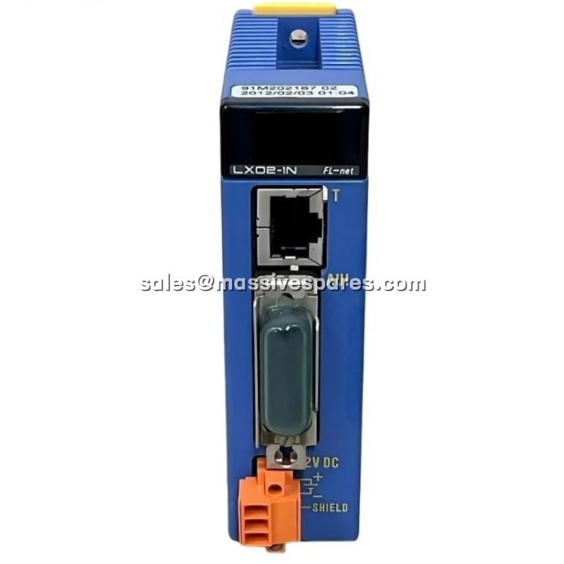
| Product Category | FL-net (OPCN-2) interface module for FA-M3 PLC |
| Protocol Standard | FL-net (OPCN-2) Version 2.00, open FA network standard |
| Transmission Speed | 10 Mbps (10BASE-T) / 100 Mbps (100BASE-TX), baseband |
| Access Control | IEEE 802.3 (CSMA/CD) compliant |
| Protocol Stack | UDP/IP, FA link, ICMP, ARP |
| Physical Interface | 1 × RJ45 connector (10BASE-T / 100BASE-TX) |
| Maximum Segment Length | 100 m between module and hub |
| Transmission Distance | 500 m at 10 Mbps; 205 m at 100 Mbps |
| Maximum Cascade Connections | 4 (using repeater hubs); determined by switch-hub specification when using a switching hub |
| Number of Connected Nodes | 254 maximum (one module counts as one node) |
| Number of Installable Modules | 6 maximum per FA-M3 main unit; modules cannot be installed in a sub-unit |
| Cyclic Transmission | 512 words in area 1; 8192 words in area 2 |
| Message Transmission | 1024 bytes maximum |
| Current Consumption | 330 mA maximum |
| External Dimensions | 28.9 (W) × 100 (H) × 83.2 (D) mm, excluding protrusions |
| Weight | 100 g |
| Operating Temperature | 0 to 55 °C |
| Storage Temperature | -20 to 75 °C |
| Operating Humidity | 10 to 90 %RH (non-condensing) |
| Storage Humidity | 10 to 90 %RH |
| Surrounding Atmosphere | Free of corrosive gas, flammable gas and heavy dust |
| Compatible CPU Modules | F3SP28-3N, F3SP38-6N, F3SP53-4H, F3SP58-6H (revision 05.00 or later); F3SP22-0S, F3SP28-3S, F3SP38-6S, F3SP53-4S, F3SP58-6S, F3SP59-7S, F3SP66-4S, F3SP67-6S, F3SP71-4□, F3SP76-7□ (all revisions) |
| Engineering Software | WideField3 (ToolBox SF66□ family) for parameter setup, monitoring and diagnostics |
| Configuration Method | IP address setup switches, condition setup switch, WideField3 setup tool, ladder program, or write network-parameters request message |
| Link Devices | 8192 link relays (L) and 8192 link registers (W) maximum per module |
| LED Indicators | RDY (ready), LNK (network participation), COM (data send/receive), ERR (fatal error / invalid setup) |
| Mounting | FA-M3 standard I/O slot; do not install in a sub-unit |
| Node Number Range | 1 to 254; node numbers 250 to 254 are reserved for maintenance software |
| Replacement Relationship | Successor to F3LX02-1N; replacement for discontinued F3LX01-0N |