
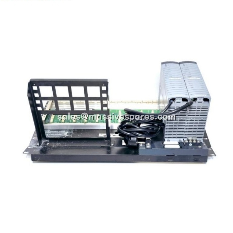
Description
The ANB11D-225 is a dual-redundant optical ESB (Extended Serial Bus) node unit manufactured by Yokogawa Electric Corporation for the CENTUM VP distributed control system. It is the slave-side node of an optical ESB bus segment and serves two functions at once: it converts field-side electrical ESB communication into optical signals and back again, and it supplies backplane power to the FIO (Field I/O) modules mounted in its own slots.
The model suffix defines the build precisely: the first digit -2 specifies a dual-redundant power supply configured for a 5 km optical repeater, the second digit 2 specifies a 220–240 V AC power input, and the final digit 5 denotes the basic type with no explosion protection. The ANB11D-225 is therefore the 5 km, 220 V AC, non-explosion-protected version of the ANB11D family.
In a CENTUM VP architecture, the ANB11D-225 is not a controller and does not execute control logic. It is the physical and electrical infrastructure that allows a Field Control Unit — specifically an AFV30□ or AFV40□ — to reach an I/O rack located several kilometres away without copper ESB cabling. Field analog I/O signals and contact I/O signals from the local FIO modules are passed to the FCU across the optical ESB bus; the same path carries control outputs back to the field. Up to eight FIO modules can be mounted in the node unit, and the 5 km optical span removes the 100 m practical limit of electrical ESB wiring while providing full galvanic isolation between the control building and the remote I/O enclosure.
Application Scenarios
A refinery was relocating its main control building and consolidating several unit control rooms. The new building was 3.8 km from the existing crude-distillation field junction cabinets, and the original electrical ESB cabling could not cover that distance without repeaters and new duct routes. Running multi-core copper also raised concerns about lightning and earth-potential differences between the two sites. The project team installed an ANB11D-225 in the existing remote instrument enclosure, retained the original FIO modules and termination assemblies, and connected the node unit to an ANT401 master module in the FCU through a pair of single-mode optical fibers. No field wiring was changed at the termination level, and the FCU continued to see the same I/O image it had before the move.
The configuration paid off during the first thunderstorm after commissioning. A lightning event at the remote site produced a large potential rise in the field earthing system, but the optical path between the FCU and the ANB11D-225 carried no ground reference and no induced current. Communication was unaffected, and there was no common-mode voltage path back to the control building electronics. Six months later, when a site electrician inadvertently opened one of the two AC supply feeders during maintenance, the second power supply in the ANB11D-225 carried the load without interruption; the FIO scan, the optical link and the control loops continued, and the only evidence of the event was a power-supply diagnostic message at the operator station. That is the working difference between distributed I/O and remote I/O that is genuinely fault-tolerant.
Parameter
| Main Parameters | Value / Description |
|---|---|
| Product Model | |
| Manufacturer | Yokogawa Electric Corporation (横河電機), Japan |
| Product Category | Node unit for dual-redundant ESB bus with optical repeater (for N-IO / FIO) |
| Suffix -2 | Dual-redundant power supply for 5 km optical repeater (pairs with ANT401-□0 / -□3) |
| Suffix 2 | 220–240 V AC power supply, 50/60 Hz |
| Suffix 5 | Basic type with no explosion protection |
| Compatible FCU | AFV30□, AFV40□ (connection via EC401 or EC402 and ANT401/ANT411) |
| Applicable I/O | N-IO and FIO modules; up to 8 modules per node unit |
| Optical Repeater Slave Modules | ANT502 (5 km) / ANT512 (5 km to 50 km) |
| Maximum Transmission Distance | 5 km with ANT401 master + ANT502 slave; up to 50 km with ANT411 + ANT512 |
| Power Consumption | 230 VA / 120 W maximum (220–240 V AC input) |
| Power Supply Redundancy | Dual-redundant AC input; automatic load transfer on one feeder failure |
| Connector Unit Options | /BU2A ESB bus connector unit; /BU2B ESB bus connector unit with terminator |
| Environmental Monitoring Option | /HU2A, /HU2B connector units with HKU (Housekeeping Unit) interface |
| HKU Monitoring Capability | Reports cabinet temperature and fan status to the FCU for central alarming |
| Available Option Codes | /BU2A, /BU2B, /HU2A, /HU2B, /NDEL, /ATDOC |
| Overall Dimensions (W × H × D) | 482.6 × 221.5 × 205 mm (approx.; 19-inch rack width) |
| Mounting | 19-inch rack mounting, 4 × M5 screws |
| Standard Accessory | Insulating bush S9049PM-4 |
| Weight | Approx. 10 kg including 8 mounted I/O modules |
| Installation Requirement | Must be installed in a keyed metallic cabinet to satisfy safety and EMC standards |
| Operating Temperature | 0 to 60 °C as basic type; -20 to 70 °C with the ISA G3 / temperature option |
| Storage Temperature | -20 to 75 °C (basic type) |
| Operating Humidity | 5 to 95 %RH, non-condensing |
| Standards Compliance | CE, CSA/NRTL/C, C-Tick, KC; Non-Incendive (CSA/FM) and Type n for selected supply options |
| Explosion Protection | Basic type none; /ATDOC available for ATEX/IECEx documentation requirements |