Application Scenarios
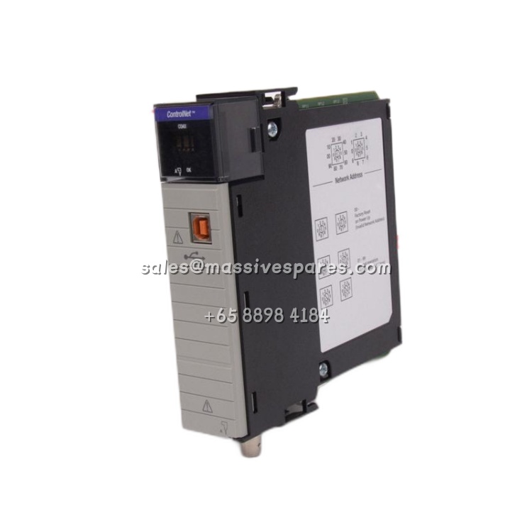
A panel builder assembling a CompactLogix control cabinet for a conveyor sorting system discovers that the required 1769 I/O modules—digital inputs for photoeyes, relay outputs for diverter solenoids, and analog cards for variable-frequency drive speed reference—cannot all fit on a single bank within the available enclosure depth. The 1769-CRR1 allows the engineer to split the I/O into two banks: the primary bank containing the controller and high-density digital cards, and a second bank mounted on a lower sub-panel containing the relay outputs and analog modules. Because the cable connects right side to right side, the second bank is physically positioned to the right of the first, maintaining the bus signal integrity over the short 305 mm run without requiring a separate communication adapter or network drop.
Parameter
| Parameter | Value/Description |
|---|---|
| Product Model | 1769-CRR1 |
| Manufacturer | Allen-Bradley / Rockwell Automation |
| Product Category | Compact I/O Bus Expansion Cable |
| Connection Type | Right-to-Right |
| Cable Length | 0.3 m (1 ft / 305 mm) |
| Compatibility | 1769 Compact I/O; MicroLogix 1500 systems |
| Operating Temperature | 0…60 °C (32…140 °F) |
| Maximum Banks per System | Up to 3 banks (using a maximum of 2 cables) |
| Power Requirement | Each additional bank requires its own power supply |
| Included Accessories | Terminating caps |
Technical Principles and Innovative Values
- Bank Splitting Without Additional Communication Hardware: The 1769-CRR1 extends the 1769 backplane bus directly, meaning the second bank of I/O modules communicates with the controller at the same native bus speed as modules in the primary bank. This differs from distributed I/O architectures that require an EtherNet/IP adapter and introduce network latency. For applications requiring tight deterministic control across 10 to 16 modules, the cable provides a simpler, lower-latency path than distributing I/O across a network.
- Right-to-Right Orientation Preserves Cabinet Layout Logic: The cable connects the right side of one bank to the right side of the next, which means the second bank physically sits to the right of the first when viewed from the front. In practice, this orientation matches the natural left-to-right reading order of a control panel drawing and allows the second bank to be mounted at a different elevation or on a hinged sub-panel while maintaining the correct bus termination. The terminating caps included with the cable protect the exposed bus connectors on the final bank.
- Defined System Limits Prevent Misapplication: Rockwell specifies that a maximum of two 1769-CRR1 (or equivalent) cables can be used in a single 1769 system, creating up to three I/O banks. Each bank beyond the first requires its own power supply because the bus cable carries communication signals only, not backplane power. This constraint is intentional: it ensures that voltage drop across the bus does not degrade module performance, and it gives panel designers a clear boundary for when to transition from a single-bank layout to a distributed I/O architecture.