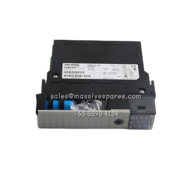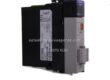
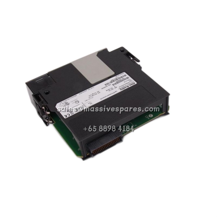
Application Scenarios
Imagine a chemical dosing skid where three pressure transmitters, two magnetic flow meters, and two level instruments all speak 4–20mA—the universal language of process instrumentation. In a conventional panel, each transmitter’s current loop would require a precision 250Ω resistor to convert the signal to 1–5V, plus an isolated analog input card, plus careful attention to grounding so that the loop powered instruments do not fight each other through the backplane. The Allen-Bradley 1771-IL/C collapses that signal chain: the transmitter lands directly on the terminal block, the module’s internal 250Ω burden resistor develops the voltage, and the 13-bit A/D converter delivers a stable digital value to the PLC-5 processor. One module, eight loops, no external hardware.
In a municipal water treatment plant, the 1771-IL/C monitors the exact signals that determine whether the plant is in compliance: chlorine residual analyzers, turbidity meters, filter bed differential pressure, and chemical feed flow. These are not signals where “close enough” is acceptable—a 1% error in chlorine residual reporting can trigger a regulatory violation. The module’s 5 ms conversion time means that a sudden drop in chlorine feed shows up in the control program almost immediately, allowing the PLC-5 to close a control valve before the residual falls out of spec. For the instrumentation technician, the 2500V RMS optical isolation is the real story: it breaks ground loops between instruments powered from different electrical services, which is the single most common cause of erratic analog readings in mixed-vendor process plants.
Parameter
| Main Parameters | Value / Description |
|---|---|
| Product Model | Allen-Bradley 1771-IL/C (Series C); 1771-IL/D (Series D, enhanced) |
| Manufacturer | Rockwell Automation / Allen-Bradley |
| Product Category | Analog Current Input Module, 8 channels |
| Input Signal Range | 4–20mA (standard instrument current loop) — direct connection to 2-wire and 4-wire transmitters |
| Number of Inputs | 8 single-ended inputs, one isolated group with common return |
| A/D Resolution | 13-bit (1771-IL/C); 15-bit (1771-IL/D) — finer granularity for the later revision |
| Conversion Time | 5ms per channel (1771-IL/C); real-time sampling configurable (1771-IL/D) |
| Internal Burden Resistor | 250Ω — converts 4–20mA to 1–5V internally; no external resistor required |
| Accuracy | ±0.1% of full scale (1771-IL/C); ±0.05% FS (1771-IL/D) — predictable, traceable measurement |
| Isolation Voltage | 2500V RMS optical isolation field-to-backplane; 500V DC group-to-group |
| Common Mode Voltage | ±10V (1771-IL/C); ±250V DC (1771-IL/D) — rejects ground potential differences |
| Backplane Current | 1.25A at 5V DC — plan chassis power supply capacity accordingly |
| Chassis Compatibility | 1771-A2B, 1771-A3B, 1771-A4B (PLC-5/20), 1771-B8; not for 1771-A1B or 1771-A5B |
| Module Footprint | Single slot, 1771 form factor; 3.25 in. × 6.88 in. × 10.12 in. approx. |
| Operating Temperature | 0°C to 60°C (32°F to 140°F) — standard industrial panel rating |
| Key Enhancement (IL/D) | Open-wire detection, selectable real-time sampling mode, 1771-NIS analog status image |
| Additional IL/D Modes | Rate-of-change, alarm limits, deviation, calibration, square-root extraction, output % |
Technical Principles and Innovative Values
Innovation Point 1 – Integrated 250Ω Burden Resistor Eliminates External Conversion Hardware: The Allen-Bradley 1771-IL/C builds the precision 250Ω burden resistor directly onto the module, converting the 4–20mA loop current into a 1–5V drop that the A/D converter measures. This is the difference between landing a transmitter on one terminal block and wiring an external resistor network, power supply, and shielding scheme. For an eight-loop application, the module removes up to eight external resistors and their associated wiring—while guaranteeing that the burden resistance stays precisely at 250Ω across temperature.
Innovation Point 2 – Optical Isolation Breaks Ground Loops at the Source: All eight channels sit behind a 2500V RMS optical isolation barrier between the field side and the backplane. In a process plant where transmitters may be powered from different electrical panels, ground potential differences of several volts are common—and they corrupt analog readings when the loops share a backplane return. The optical barrier means each loop’s current is measured independently of the controller’s reference potential, so the 4–20mA signal arrives at the processor exactly as the transmitter sent it.
Innovation Point 3 – 5ms Conversion Time Supports Real Closed-Loop Control: The 1771-IL/C completes an A/D conversion in 5ms per channel. Across eight channels this gives a full scan of the process variables in 40ms—fast enough that a PLC-5 PID loop can react to a pressure or flow upset within one or two program scans. Compare this to a module that takes 100ms per channel, and the difference is the difference between controlling the process and merely observing it.
Innovation Point 4 – Later Revision Adds Diagnostic Intelligence, Not Just Conversion: The 1771-IL/D revision transforms the module from a passive converter into a diagnostic asset. Open-wire detection identifies a broken transmitter lead or disconnected terminal before the process value drifts into an uncontrolled state. The 1771-NIS analog status image exposes per-channel health to the control program, while selectable real-time sampling mode lets the engineer choose between synchronized sampling (all channels captured simultaneously) and sequential sampling (lower noise). Rate-of-change, alarm limits, deviation, calibration, square-root extraction, and output-percent functions execute on the module rather than consuming PLC-5 scan time.
Innovation Point 5 – Single Common Return Reduces Wiring While Maintaining Isolation: The eight channels share one common return terminal, so eight 4–20mA loops require nine field wires rather than sixteen. Because the entire group is isolated together, this does not compromise the isolation benefit—it simply recognizes that most process installations already share a common instrument ground. The result is a noticeably cleaner terminal strip and fewer opportunities for wiring errors during installation and maintenance.