Product Overview
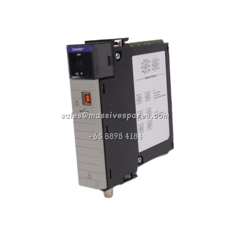
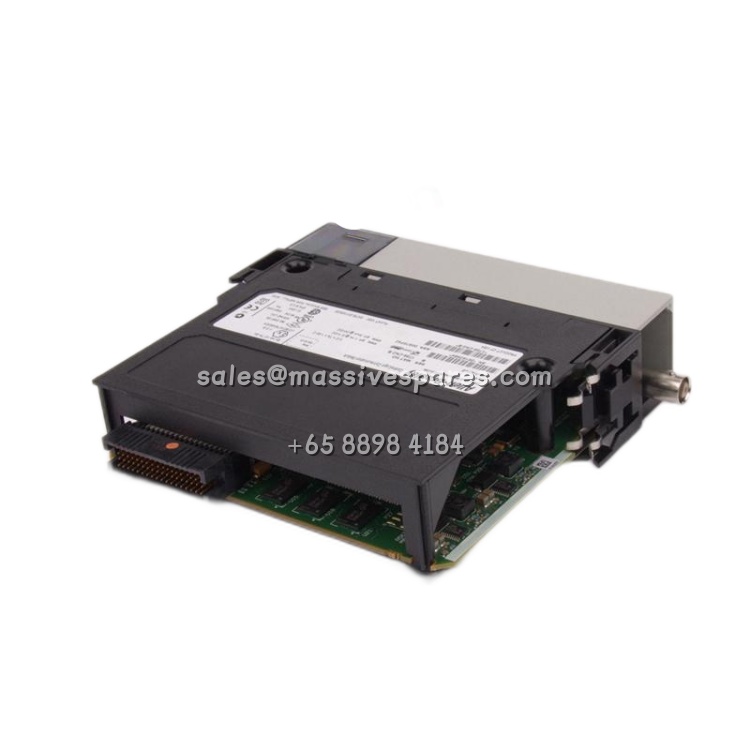
The Allen-Bradley 1794-TB3G is a grounded screw-clamp terminal base unit within the 1794 FLEX I/O family developed by Rockwell Automation, engineered specifically for analog modules and applications where individual field-side grounding is required. Mounted on a 35 mm DIN rail immediately to the right of a FLEX I/O adapter, the 1794-TB3G provides the physical termination points for all incoming and outgoing field wiring while simultaneously forming the segment of the FLEXBUS backplane that carries communication and power between the adapter and installed I/O modules.
Offering 36 I/O connections, 2 common terminals, 2 +V terminals, and — critically — 10 dedicated chassis-ground terminals, the 1794-TB3G solves a long-standing integration challenge for analog instrumentation: how to land shield drains and signal-return references without compromising measurement integrity. This makes it the standard companion base for FLEX analog input and output modules that demand a grounded termination scheme, including thermocouple, RTD, millivolt, current, and voltage families. Because field wiring terminates on the base rather than the module, the electronics module can be removed and replaced without disturbing a single conductor, dramatically reducing mean time to repair in live installations.
Electrically, the 1794-TB3G carries up to 10 A per terminal at 31.2 V DC/AC (50/60 Hz) with a continuous isolation rating of 50 V between field wiring and FLEXBUS, while the backplane segment passes 5 V DC at 640 mA to the module slot. Screw-clamp terminations accept 0.21–1.3 mm² (AWG 24–16) wire at a torque of 0.56–0.79 Nm, and the compact 94 × 94 × 69 mm footprint keeps panel density high even on crowded DIN rails. Compatible with FLEX, FLEX Ex, and FLEX XT I/O systems, the 1794-TB3G is routinely specified in process skids, water and wastewater treatment plants, chemical dosing systems, and OEM machinery wherever analog instrumentation must be grounded cleanly, serviced quickly, and reconfigured without panel redesign — a combination that has kept it in continuous demand across industrial retrofit and sustainment programs for decades.
Technical Specifications
| Parameter Name | Parameter Value |
|---|---|
| Product Model | 1794-TB3G |
| Manufacturer | Allen-Bradley (Rockwell Automation) |
| Product Type | FLEX I/O Terminal Base Unit (Grounded Screw Clamp) |
| Compatible Systems | 1794 FLEX, FLEX Ex, FLEX XT I/O |
| I/O Connections | 36 I/O terminals |
| Common Terminals | 2 |
| +V Terminals | 2 |
| Chassis Ground Terminals | 10 (individual grounding) |
| V/COM Terminal Rating | 31.2 V DC/AC, 50/60 Hz, 10 A |
| FLEXBUS Supply | 5 V DC, 640 mA |
| Isolation Voltage | 50 V continuous, field wiring to FLEXBUS |
| Wire Size Range | 0.21–1.3 mm² (AWG 24–16) |
| Terminal Screw Torque | 0.56–0.79 N·m (5–7 lb·in) |
| Termination Style | Screw clamp |
| Dimensions | 94 × 94 × 69 mm |
| Mounting | 35 mm DIN rail (snap-on, right of adapter) |
| Operating Temperature | 0 °C to 55 °C |
| Certifications | CE, UL 508, CSA |
Main Features and Advantages
The defining engineering feature of the 1794-TB3G is its ten-terminal dedicated chassis-ground row, which addresses the grounding discipline that analog measurements demand. Shield drains, signal-reference conductors, and ground-bond jumpers land on their own terminals rather than sharing I/O or common positions, so induced noise, ground loops, and shield shorting — the three most common causes of analog reading drift — are physically prevented at the panel level. For plants that audit instrumentation quality or pursue Six-Sigma measurement accuracy, this built-in grounding structure is often the deciding factor between the 1794-TB3G and a generic 16-I/O base.
Mechanical design follows the plug-in FLEX philosophy that makes the whole 1794 family attractive for maintenance-driven operations. All field wiring terminates on the base, and the matching FLEX I/O module simply snaps on top, forming both the electrical interface and the FLEXBUS connection. When an analog module fails, a technician pulls it off the base and clicks in a replacement — no wires are touched, no shield terminations are disturbed, and no ladder-logic reconfiguration is required if the replacement carries the same catalog number. The result is a module swap measured in minutes rather than the hour or more that hard-wired chassis-based I/O demands.
Screw-clamp terminations on the 1794-TB3G provide the broadest compatibility with plant wiring practices, accepting solid, stranded, and ferruled conductors from 0.21 to 1.3 mm². The 0.56–0.79 N·m torque specification matches standard industrial driver settings, and each terminal is clearly silkscreened for unambiguous wiring documentation. Because the bases snap together on the DIN rail, the FLEXBUS connection is established mechanically during installation — no ribbon cables, no separate backplane assembly, and no custom bus wiring between slots.
The grounded-base construction of the 1794-TB3G also makes it the natural companion for FLEX Ex and FLEX XT variants deployed in hazardous or extended-temperature environments, where grounding continuity is verified during commissioning audits. Its 31.2 V DC/AC, 10 A terminal rating comfortably covers 24 V DC analog loops and low-voltage discrete signals alike, while the 50 V continuous isolation rating preserves safe separation between field wiring and the internal FLEXBUS. For integrators standardizing on a single terminal base across a mixed digital and analog FLEX installation, the 1794-TB3G offers a grounded, analog-ready, screw-clamp solution that remains in production and readily available as new or surplus stock for sustaining mature panels.