Description:
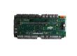
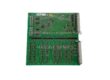
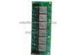
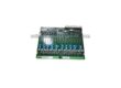
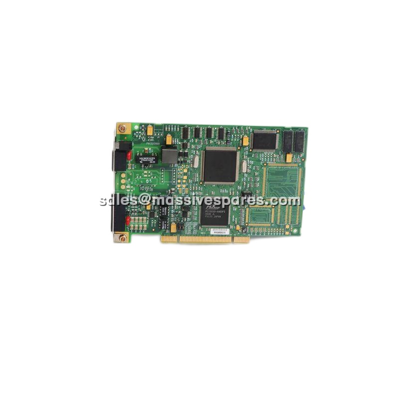
The 80190-480-01-R is an Allen-Bradley / Rockwell Automation drive control board — the central control PCB for the PowerFlex 7000 medium-voltage AC drive platform. It executes drive logic, processes feedback from current and voltage transducers, generates gate firing commands for the power semiconductors, and manages the digital I/O that connects the drive to field interlocks, permissives and monitoring circuits.
It is catalogued as a revised “‑R” release and cross-referenced against 80190-478-51, giving most installations a drop-in upgrade path without firmware re-flashing. The part is discontinued by the manufacturer and is now sourced through surplus, refurbished and specialist aftermarket channels.
Two points buyers should hold onto. First, the published electrical figures — 480 VAC, 15 A, 7.2 kW — describe the board’s own control-power class and I/O capability, not the medium-voltage power stage of the PowerFlex 7000, which operates at 2.4 kV to 6.6 kV with motor currents up to 720 A. Second, the 80190-480-01-R occupies a dedicated primary control slot in the drive’s control chassis; where a redundant configuration is specified, a second board is installed in the redundant slot and the pair performs automatic health-monitored switchover. Confirm which configuration your drive uses before ordering, because it determines whether you need one board or two.
Application Scenarios:
A mine’s primary slurry pump is driven by a PowerFlex 7000 medium-voltage drive that has been running for eighteen years. One morning the drive faults on a control board error and will not reset. There is no spare on site, the OEM lead time is measured in weeks, and the pump feeds a circuit whose outage stops the whole concentrator. Every hour of downtime is being counted in six figures, and the “obvious” answer — replace the drive — means a new power structure, new control platform, new commissioning and a capital submission that will not clear before the next quarter.
This is the scenario the 80190-480-01-R exists to resolve. Because it is the correct control board for the installed platform, it restores the drive to service without touching the power structure, the motor, the cooling system or the application parameters. The replacement is a board swap in the control chassis, not a drive replacement — and the outage moves from weeks to hours.
The second scenario is the one that makes a spare worth holding. On a water treatment intake pump or a pipeline booster, the drive is often configured for redundant control: two 80190-480-01-R boards, one primary and one standby, with automatic switchover if the primary stops providing stable output. In that configuration, a board failure is an event in the system event list rather than a production stop. But it is also an event that leaves the drive running on a single board — degraded, unprotected, and one failure away from the outage described above. Holding a verified 80190-480-01-R on the shelf is what converts an unnoticed degradation back into a protected configuration inside a single maintenance window.
Parameter:
| Main Parameters | Value/Description |
|---|---|
| Product Model | 80190-480-01-R (also written 8019048001R) |
| Manufacturer | Allen-Bradley / Rockwell Automation |
| Product Category | Drive control board — main control PCB for a medium-voltage AC drive |
| Compatible Platform | PowerFlex 7000 medium voltage AC drive (2.4 kV – 6.6 kV class; motor currents to 720 A) |
| Cross-Reference | 80190-478-51 — the 80190-480-01-R is the revised “‑R” release, generally a drop-in replacement |
| Input Voltage | 480 VAC (control-power class for the board) |
| Current Rating | 15 A |
| Power Rating | 7.2 kW |
| Motor Control Capacity | Up to 4 motors coordinated from a single control point |
| Digital I/O | 16 digital inputs and 16 digital outputs — 32 discrete points total |
| I/O Isolation | Approximately 500 VDC channel-to-channel (as published) |
| Core Function | Drive logic execution, motor start/stop sequencing, speed and torque regulation, feedback monitoring, interlock processing, gate firing command generation |
| Slot Assignment | Dedicated primary control slot in the PowerFlex 7000 control chassis (far-left control board position); second board in redundant slot for dual redundant control |
| Redundancy | Automatic health-monitored switchover in dual redundant configuration, with an entry placed in the system event list |
| Communication | ControlNet / DeviceNet / EtherNet/IP depending on drive configuration |
| Physical Data | Approximately 27.8 × 21.4 × 2.8 cm board; shipping figures around 30.2 × 25 × 2.5 cm; weight approximately 0.42 kg (0.93 lb) |
| Environmental Rating | 0 °C to +40 °C or 0 °C to +55 °C depending on source; storage −40 °C to +85 °C; 5–95% RH non-condensing |
| Lifecycle Status | Discontinued by the manufacturer — available as surplus, new-old-stock or professionally refurbished |
Technical Principles and Innovative Values:
Innovation Point 1: Closed-loop conversion of feedback into gate firing commands.
The 80190-480-01-R continuously processes feedback from motor encoders, current sensors and voltage transducers and converts those inputs into precise gate firing commands for the drive’s power semiconductors. That closed loop is what turns a medium-voltage power structure into a controlled drive capable of soft starting, variable speed operation, torque regulation and controlled stopping on both induction and synchronous machines.
Innovation Point 2: Multi-motor coordination from one control point.
The board can coordinate up to four motors, which removes the need for multiple independent drive controllers in applications where several machines share a process duty — grouped fans, multi-pump stations, coordinated conveyor sections. Fewer controllers mean fewer control platforms to configure, licence, maintain and eventually replace.
Innovation Point 3: High discrete density without expansion hardware.
With 16 digital inputs and 16 digital outputs on board, the 80190-480-01-R lets engineers wire permissives, safety interlocks, field sensors, relay outputs and monitoring circuits directly into the drive’s control loop. That eliminates external I/O blocks, their power supplies, their wiring and their commissioning time — and it keeps interlock logic resident in the drive rather than distributed across added hardware.
Innovation Point 4: Automatic switchover in a dual redundant configuration.
When two 80190-480-01-R boards are installed, the pair continuously monitors the health of both. If the primary stops providing stable output outside configured tolerance, control transfers automatically to the secondary and the event is logged. This is availability engineering at board level: the single most likely electronic failure in the drive no longer stops the process, provided the degraded state is noticed and corrected.
Innovation Point 5: A revision path that does not require re-engineering.
The 80190-480-01-R is the revised release of 80190-478-51 and, in most configurations, drops in without firmware re-flashing. For an operator holding an ageing drive, that means the replacement path forward is a part number change rather than a platform change — the difference between a purchase order and a project.
Innovation Point 6: Isolation that protects control electronics from power-stage noise.
With channel-to-channel I/O isolation around 500 VDC, the 80190-480-01-R keeps field wiring transients from migrating into the control electronics. In a medium-voltage environment where the power stage switches kilovolts and hundreds of amps a few centimetres away, that barrier is what makes stable, repeatable control possible at all.