Application Scenarios
A chemical plant relied on a large induced-draft fan for continuous operation. The motor had survived several high-temperature summers, but maintenance records showed longer acceleration times, higher running currents and occasional thermal trips. Nameplate-based settings no longer reflected the machine’s actual condition, while operations were reluctant to increase trip margins because that could delay protection during a real stall.
The plant installed a GE Multilin 369-HI-R-M-0-0 with RTD and metering capability. The relay monitored phase current, ground current, voltage-related quantities, stator temperature and bearing temperature, while learning the motor’s acceleration and cooling behavior. When a developing blockage increased fan loading, the relay provided an early alarm instead of waiting for a full thermal trip.
This case illustrates the real value of the 369-HI-R-M-0-0: it converts protection from a fixed setting into a condition-based decision. That allows maintenance to intervene during a planned outage rather than discovering motor damage after an unexpected shutdown.
Parameter
| Main Parameters | Value / Description |
|---|---|
| Product Model | 369-HI-R-M-0-0 |
| Manufacturer | GE Multilin |
| Product Category | Digital motor management relay |
| Model Code | 369 base; HI human interface; R twelve RTD inputs; M metering; 0 no fiber port; 0 no optional protocol interface |
| Control Power | HI option: 50–300 V DC or 60–265 V AC at 50/60 Hz |
| Control Power Consumption | 20 VA nominal; 65 VA maximum |
| Current Inputs | Three phase-current inputs with 1 A or 5 A secondary selection |
| Current Measurement | True RMS with approximately 1.04 ms sampling |
| Ground-Current Input | 1 A / 5 A CT input or sensitive 50:0.025 zero-sequence CT input |
| Input Frequency | 20–100 Hz |
| RTD Inputs | 12 three-wire RTD inputs |
| RTD Types | Pt100, Ni100, Ni120 and 10 Ω copper |
| Digital Inputs | 6 optically isolated inputs |
| Output Relays | 4 Form C contacts: trip, alarm and two programmable auxiliary outputs |
| Analog Outputs | 4 isolated outputs; 0–1 mA, 0–20 mA or 4–20 mA |
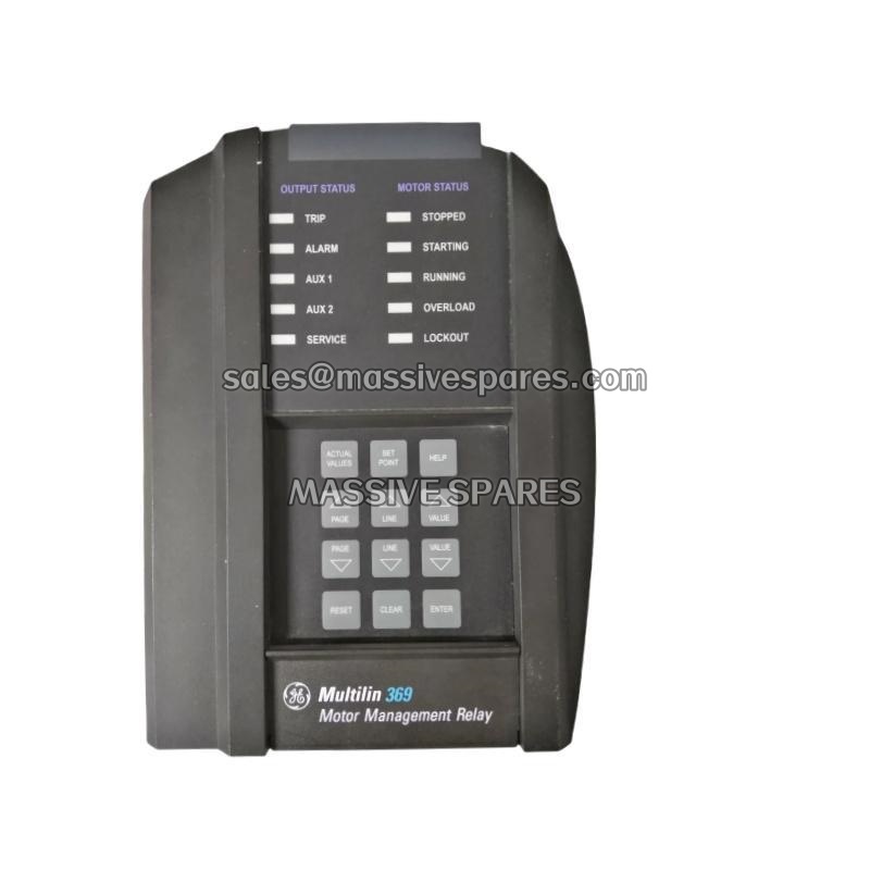
| Display | 40-character backlit LCD with keypad and motor-status LEDs |
| Protection Functions | Thermal overload, phase overcurrent, ground fault, unbalance, phase loss, underload, stall or jam, undervoltage, overvoltage, underfrequency, phase reversal and start supervision |
| Overload Curves | 15 standard curves plus user-programmable FlexCurve |
| Metering | Voltage, current, real power, reactive power, apparent power, power factor, frequency and energy |
| Event Recording | 512-event recorder with timestamps |
| Oscillography | 3 records of 16 cycles each |
| Communication | 1 front RS232 port and 3 rear RS485 ports; Modbus RTU |
| Configuration Software | EnerVista 369 Setup |
| Operating Temperature | −40 °C to +60 °C |
| Storage Temperature | −40 °C to +80 °C |
| Humidity | Up to 95% relative humidity, non-condensing |
| Mounting Method | Panel-mount, non-drawout installation |
| Dimensions | Approximately 296 × 107 × 205 mm |
| Weight | Approximately 4.5 kg |
| Certifications | UL, CSA and CE, subject to the label fitted to the supplied unit |