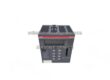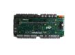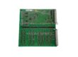
1. Scope & Objective
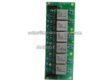
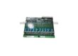
When critical industrial process lines depend on legacy distributed control systems (DCS), acquiring discontinued or surplus hardware is standard practice. However, unvetted inventory introduces catastrophic risks of bus failure or line shutdown. This protocol defines mandatory bench-level verification before entering any board into active spares inventory.

Sourcing Obsolete DCS Modules: Technical Inbound Inspection Protocol
2. Physical & Anti-Static Verification Checklist
All inspections must take place in an ANSI/ESD S20.20 certified environment with grounded wrist straps and conductive matting:
- [ ] Packaging Integrity: Ensure the module arrived in a sealed static-shielding bag (MIL-PRF-81705) with active moisture desiccant.
- [ ] Housing & Alignment: Inspect rack slide guides, locking tabs, and terminal screws for mechanical fatigue or hairline stress fractures.
- [ ] Backplane Pin Integrity: Examine rear male/female multi-pin DIN connectors under magnification for pin alignment, bending, or copper oxidation.
- [ ] Onboard Power Reservoirs: Visually inspect all electrolytic capacitors for bulging vents, venting residue, or tilted mountings.
CRITICAL WARNING — COMPONENT DEGRADATION
Units stored in unconditioned depots for over 60 months frequently exhibit dielectric breakdown in aluminum capacitors and depleted lithium backup cells. A flat battery (<3.0V DC) erases board configuration upon power-down.
3. Power-On & Backplane Handshake Testing
Connect the card to an isolated, current-limited test backplane:
- Cold Resistance Measurement: Verify input power terminals exhibit no direct short circuit to chassis ground (>20 MΩ at 500V DC).
- Boot Sequence Verification: Monitor power-on self-test (POST) LEDs. A persistent red fault indicator or watchdog trip signals memory parity corruption.
- Channel Impedance Calibration: For analog I/O cards, sweep test points across 4–20 mA or 1–5 V DC ranges. Measured linearity drift must not exceed manufacturer tolerances (typically ±0.1% FSR).
- Firmware Matching: Cross-check internal EEPROM/EPROM revision numbers against site plant standards.
Sign off the incoming inspection report and apply a tamper-evident serial sticker prior to storage.
(Character count: ~2,050 characters)
Article 02
Title: Troubleshooting Redundancy Desynchronization on DCS Controller Cards
Format Style: Technical Diagnostic Flow & Terminal Status Log
Target Audience: Control Systems Engineers, Automation Field Technicians
System Alert: Primary / Standby Sync Failure
In high-availability automation architectures (e.g., Honeywell Experion C300, Emerson Ovation, Yokogawa Centum VP), redundant processor pairs guarantee zero-downtime bumpless transfer. When the synchronization bus degrades, processors lose track of memory registers, escalating to dual-controller lockup.
+-------------------------------------------------------------+
|               PRIMARY CONTROLLER (ACTIVE)                   |
|                   Status: RUN | SYNC FAIL                   |
+------------------------------+------------------------------+
                               | High-Speed Redundancy Link
                               v
+-------------------------------------------------------------+
|               BACKUP CONTROLLER (STANDBY)                   |
|                   Status: HALT / MEM_MISMATCH               |
+-------------------------------------------------------------+
Diagnostic Execution Steps
Step 1: Status Word Interrogation
Query the processor diagnostic registers via the engineering workstation terminal:
Plaintext
DIAG> read_reg --slot 03 --reg 0x4F00
R01: 0x8021 [ACTIVE_MASTER]
R02: 0x0004 [REDUNDANCY_FAULT: FIBER_JITTER]
R03: 0x1102 [MEM_DESYNC_OFFSET: 0x00FF8C]
A non-zero redundancy fault code points directly to hardware synchronization latency rather than logic execution failure.
Step 2: Physical Communication Link Audit
- Optic Cable Attenuation: Check LC-LC multi-mode fiber transceivers using an optical power meter. Insertion loss exceeding -3.0 dBm creates packet collisions during high-speed cycle replication.
- Backplane Tracking: Inspect backplane redundancy bridge channels for thermal degradation or pin corrosion.
Step 3: Firmware & Boot ROM Parity
Redundant pairs must execute identical firmware revisions, down to minor build letters. If replacing an aged secondary card with a surplus unit, check the EPROM sticker. Flashing firmware online during active process execution is prohibited; mismatching firmware blocks memory state mirroring.
Step 4: Managed Hot-Swap Procedure
- Confirm the primary card holds a steady RUN/OK status and controls all I/O racks.
- Seat the replacement standby unit into the unpowered redundant slot until the ejector levers snap shut.
- Observe the boot LEDs: Flashing Yellow (Initializing) -> Steady Yellow (Syncing DB) -> Steady Green (Standby Ready).
- Verify bumpless transfer readiness via the system event log.