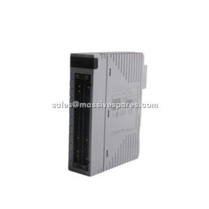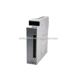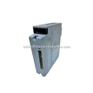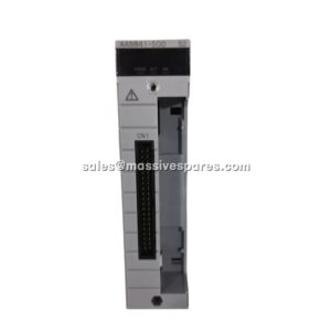

Description
Application Scenarios
A Southeast Asian ethylene plant was fighting a familiar problem: six bearing-temperature points on each of four compressor lube-oil skids, plus eight heater-skin RTDs and four catalyst-bed thermocouples, all feeding a single node unit that was already full. Splitting the job across two node units would have meant a second I/O cabinet, a second power supply and a six-week change order. Instead the team installed two AAR145-S03 S1 modules. Sixteen isolated channels per card, each configurable per channel, absorbed the bearing points and heater-skin measurements without mixing signal types or adding hardware. Because every channel is galvanically separated from the next, a damaged screen cable on one bearing probe could not shift the reading on its neighbour — an important distinction from multiplexed, non-isolated temperature input designs.
The second problem showed up three months later during the rainy season. Cabinet inlet filters had been neglected and the internal dewpoint rose. The unprotected modules in the same rack began showing unstable low-level readings; the AAR145-S03 S1 cards, with the G3 coating option, held their accuracy within specification. The plant’s instrumentation supervisor’s comment was unusually specific: “The modules we did not have to replace were the ones with the coating.” The card did not solve the housekeeping issue, but it made the difference between a maintenance inconvenience and an unplanned shutdown.
Parameter
| Main Parameters | Value / Description |
|---|---|
| Product Model | AAR145-S03 S1 |
| Manufacturer | Yokogawa Electric Corporation |
| Product Category | Analog Input Module — RTD / Potentiometer |
| Input Channels | 16 channels, all channels isolated |
| Input Signal — RTD | JIS C1604:1997 / IEC 751 Pt100, 3-wire type (JPt100 on selected variants) |
| Input Signal — Potentiometer | Total resistance 100 Ω to 10 kΩ; span resistance ≥50 % of total resistance |
| Per-Channel Signal Selection | RTD/POT selected individually for CH1 to CH16 |
| Allowable Input Voltage | ±5 V |
| Measurement Current (RTD) | 1 mA constant current — keeps self-heating below measurable levels |
| Accuracy (RTD) | ±150 mΩ |
| Accuracy (POT) | ±0.2 % of full scale |
| Allowable Wiring Resistance | 150 Ω or less per wire; IN□A and IN□B leads must be equal |
| Withstanding Voltage (input to system) | 500 V AC for 1 minute; 1500 V AC for a single card |
| Withstanding Voltage (between channels) | 200 V AC for 1 minute |
| Input Resistance | 1 MΩ or higher, both powered and unpowered |
| Data Update Period | 1 second |
| Burnout Detection | UP/DOWN/OFF selectable for all channels; detection time 60 s |
| Temperature Drift | RTD ±0.3 Ω / 10 °C; POT ±0.4 % / 10 °C |
| Maximum Current Consumption | 350 mA at 5 V DC |
| External Connection | Dedicated cable KS8 / AKB335 |
| Operating Temperature | -20 to 70 °C (S03 / G3 option) |
| Weight | Approx. 0.30 kg |
Technical Principles and Innovative Values
- Resistance measurement, not voltage interpretation. Innovation Point 1: the module does not convert millivolts. It sources a precisely controlled 1 mA current through the RTD element and measures the resulting resistance directly, then applies the Pt100 curve inside the module. At 1 mA the I²R self-heating of a 100 Ω element is 0.1 mW — small enough that the sensor does not warm itself above the process it is trying to measure. The module also retains compliance with the older JIS C1604:1989 and IEC 751:1986 (IPTS-68) curve, so a replacement card reads consistently with a system calibrated ten years ago.
- Per-channel configuration removes the need for dedicated card types. Innovation Point 2: channel 1 can be a 3-wire Pt100 bearing sensor while channel 2 on the same card is a 1 kΩ potentiometer on a slide-valve position indicator. The type is set in engineering software, not by jumpers, dip switches or card replacement. A tank-farm application with 12 RTDs and four rack-position pots therefore uses one module instead of two, and the spare on the shelf is a single part number rather than a card for each signal type.
- Isolation is the architecture, not an option. Innovation Point 3: each of the 16 channels is isolated from the next and from the system backplane, with 200 V AC channel-to-channel and 1500 V AC field-to-system withstand ratings for a single card. In a typical plant, RTD screens are bonded to different local earth references several hundred metres apart. Those references are rarely at exactly the same potential; galvanic isolation prevents the difference from becoming a measurement error or, worse, a fault path back into the DCS rack.
- Three-wire sensing eliminates lead-wire resistance without external hardware. Innovation Point 4: the 3-wire Pt100 connection uses two active leads and a return, and the measurement current is driven in a way that cancels the resistance of the copper conductors. The specification requires the two signal cable resistances to be equal and each not to exceed 150 Ω — a generous allowance that supports runs well beyond the marshalling cabinet. With matched leads, a 100 m extension adds no measurable error to the temperature reading.
- Burnout detection is a safety decision, not a checkbox. Innovation Point 5: an open-circuit RTD can drive a loop to an apparently normal low value or an apparently dangerous high one, depending on the failure. The AAR145-S03 S1 allows UP, DOWN or OFF to be selected across all channels, with a 60-second detection time. On a bearing-temperature loop, selecting UP scale drives the loop into a known high-temperature state that the interlock logic recognises; selecting DOWN scale does the opposite. Either choice is safer than leaving the decision to the transmitter and the cable.
- 1-second update is matched to thermal inertia. Innovation Point 6: temperature is a slow variable. A 1-second scan is eight times faster than the usual 8-second PID execution on thermal loops, which is more than enough for heat exchangers, reactors and bearing temperatures. Faster scanning would only produce noise to filter out. The same 1-second period is also the update rate used by the related thermocouple/mV module in the family, keeping engineering habits consistent across a project.
- Redundancy is built in, not engineered around. Innovation Point 7: the module supports dual-redundant configuration. A failed card is taken over by its partner without the control loop losing its process value, which matters most on reactor-skin and bearing-temperature arrays where losing visibility is itself a trip condition.