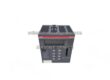
Description
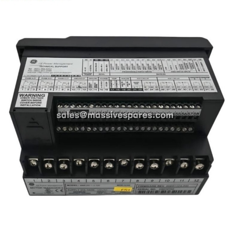
The GE MMII-PD-1-2-120 is an intelligent, microprocessor-based motor protection, control and monitoring relay from the GE Multilin Motor Manager II (MM2) family. Designed for low-voltage three-phase AC induction motors, it combines the functions normally distributed across a drawer of discrete devices in a motor control center — overload and ground-fault protection, contactor control, current and power metering, event recording, and serial communications — in one compact panel-mount unit.
In short, the MMII-PD-1-2-120 replaces the traditional assembly of a bimetallic overload relay, phase-loss relay, control timers, and separate contactor control logic with a single programmable device. Its 120 VAC control voltage, full-faceplate alphanumeric display and keypad, and Modbus RTU interface make it suitable for both local operator visibility and remote supervision from a DCS, PLC or SCADA system.
Application Scenarios
A water-treatment plant was repeatedly losing a raw-water pump to what the operators described as random overload trips. Each trip shut down the pump and required an electrician to reset the overload and a process operator to restart the sequence manually. The pump motor itself showed no obvious fault, and the paper overload relay provided no record of what the current had been in the seconds before the trip. Maintenance was left guessing whether the problem was a blocked suction line, a worn coupling, or a setting that simply did not match the motor’s true duty cycle.
The plant’s replacement approach was to install the GE MMII-PD-1-2-120 in the pump starter’s panel cutout, retaining the same 120 VAC control supply and using the existing current transformers. The difference became visible immediately. Instead of a single “tripped” indication, the relay displayed actual phase currents, ground current, thermal capacity used, and a running-hours and start-count history. The first event recorded after installation showed one phase current climbing well above the others during start-up while thermal capacity accelerated toward the trip point — a stalled or mechanically loaded start, not a winding fault. Because the MMII-PD-1-2-120 could log pre-trip data and trip statistics, the plant identified a suction-side restriction and adjusted the start sequence instead of replacing a serviceable motor. For equipment where a motor failure can stop an entire process line, that shift from a binary trip to a recorded diagnosis is what turns an unexplained outage into a solvable maintenance problem.
Parameter
| Main Parameters | Value / Description |
|---|---|
| Product Model | MMII-PD-1-2-120 |
| Manufacturer | GE / GE Multilin (now legacy GE product family) |
| Product Category | Intelligent motor management, protection and control relay |
| Product Family | Motor Manager II (MM2) |
| Mounting | P = panel mount with full-faceplate display and keypad |
| Options Fitted | D = digital inputs; 1 = Option 1 (process control); 2 = Option 2 (enhanced protection) |
| Control / Supply Voltage | 120 = 120 VAC control voltage, 50/60 Hz |
| Protection — Standard | 49/51 three-phase thermal overload and single-phase protection |
| Protection — Option 2 | 50G/51G ground fault, 48 locked-rotor / stall, 49 thermistor (PTC/NTC), 27 undervoltage, 59 overvoltage, 37 undercurrent / underpower |
| Phase Monitoring | Phase-loss (loss-of-phase) and phase-current unbalance protection |
| Analog Inputs | 4–20 mA process input(s) |
| Digital Inputs | 4 standard control inputs (Start, Stop, local isolator, Contactor A status) + 2 programmable; Option 1 adds 8 further programmable process inputs |
| Outputs | 2 contactor outputs (for two-speed, reversing, wye-delta, autotransformer and part-winding starters) + 2 programmable outputs / auxiliary relays |
| Display / Interface | 20 × 2 alphanumeric LCD with backlight and front-panel keypad |
| Communication | 2-wire RS485, Modbus RTU, 1200 to 19,200 baud |
| Metering | Three-phase current, ground current, kW, kWh and thermal capacity |
| Diagnostics & Recording | Pretrip data, historical statistics, trip/event records, running hours and start/trip counters |
| Configuration Software | GE EnerVista MMII |
| Approximate Dimensions | 188 × 112 × 127 mm (7.4 × 4.4 × 5.0 in), panel-mount chassis |
| Approximate Weight | 1.36 kg (about 3 lb) |
| Operating Temperature | 0 to 60 °C |
| Front Protection Rating | IP53 front of panel; terminal area IP20 |
| Enclosure Options | NEMA 1, 3, 3R, 4, 4X, 12, 12K available on the enclosing structure |
| Product Status | Legacy / obsolete; replacement and tested-surplus supply only |