Application Scenarios
A combined-heat-and-power plant operating a 4 MW synchronous generator experienced repeated stator insulation deterioration on the generator following excitation regulator disturbances. The original protection scheme used a single-stage overvoltage relay with a fixed instantaneous trip, which either failed to catch a slowly rising no-load overvoltage condition or, on one occasion, tripped the unit during a harmless voltage swell caused by capacitor-bank switching. After installing the MRU3-11D with a two-stage overvoltage characteristic — an alarm stage at 1.10 × Un with a 3-second delay and a trip stage at 1.20 × Un with a 0.5-second delay — the site gained a clear warning before the trip level was reached and acquired a time delay long enough to ride through the switching transient. Over the following operating season the relay logged several pre-alarm events that allowed the operators to correct the AVR trim manually, and recorded no spurious trips.
The practical role of the MRU3-11D in this application is to distinguish between a transient disturbance and a genuine fault. Generator overvoltage at no load is a recognised insulation stress mechanism: an uncontrolled AVR or loss of load can drive terminal voltage high enough to degrade stator winding insulation and increase core heating. At the same time, a protection relay that responds instantaneously to every voltage swell will create avoidable outages. The two-stage characteristic with independently set delays is the engineering compromise that protects the machine without sacrificing availability.
Parameter
| Parameter | Value / Description |
|---|---|
| Product Model | MRU3-11D |
| Manufacturer | Woodward |
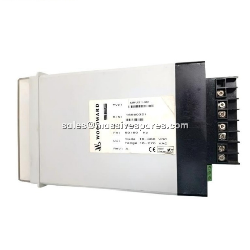
| Product Category | Microprocessor-based three-phase voltage protection / monitoring relay |
| Measurement Input | 0–690 V AC; direct connection or via external VT in star or V-connection; phase-to-phase or phase-to-neutral |
| Rated System Voltages | 100 V / 230 V / 400 V software-selectable; up to 690 V AC direct measurement |
| Measurement Principle | True RMS line voltages; positive-, negative- and zero-sequence symmetrical components |
| Measurement Accuracy | ±1% of rated voltage |
| Frequency Range | 40–70 Hz; 50 Hz / 60 Hz selectable or variable |
| Protection Functions | Two-stage overvoltage and undervoltage (U> / U>>, U< / U<<); phase unbalance and phase-sequence; negative- and zero-sequence overvoltage |
| Setting Ranges | Undervoltage 0.7–1.0 × Un; overvoltage 1.0–1.3 × Un; unbalance 5–20%; delays 0.1–10 s |
| Parameter Sets | Two complete, independently configurable parameter sets; switchable via external discrete input |
| Outputs | 1 × SPDT relay contact, 5 A at 250 V AC; 2 independent programmable alarm/trip outputs; 4–20 mA analog output for voltage indication |
| Communication | RS485, Modbus RTU; optional SEG RS485 Pro-Open Data Protocol |
| Fault Memory | Up to 8 fault occurrences with time stamp; voltage-failure-safe trip-value storage |
| Auxiliary Supply | 24 V DC (±20%) or 85–265 V AC/DC wide range |
| Display | Alphanumeric display plus status LEDs for local readout of measured values, sequence components and trip cause |
| Mounting | 35 mm DIN rail (EN 50022) or panel mount |
| Dimensions | 108 × 70 × 115 mm (approx. 4.25 × 2.75 × 4.5 in) |
| Weight | Approx. 0.4 kg |
| Operating Temperature | –20 °C to +60 °C |
| Compliance | CE, UL, RoHS; VDE 0435 Part 303 and IEC 255 |
| Suffix Meaning | 11 = standard basic type; D = trip latch (fault-hold) with manual or remote reset |