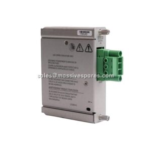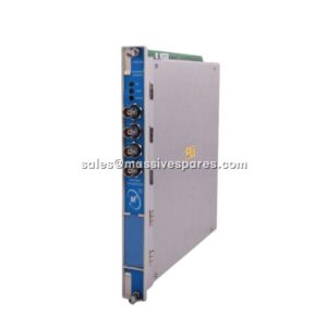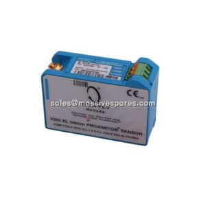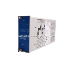

Description
Application Scenarios:
A power station has a bank of cooling tower fans and a set of balance-of-plant pump and gearbox trains that are not instrumented with proximity probes — they are casing-measurement machines, and the plant wants continuous protection on them without the cost of a full shaft-relative measurement system. Two channels per machine, velocity in mm/s, Alert and Danger relays into the plant shutdown logic, and a 4–20 mA signal back to the DCS so operations can trend casing vibration alongside everything else. That is the 3300/55.
Then comes the part that makes the filter settings matter. A fan gearbox starts showing rising velocity, and nobody can tell whether the increase is a genuine bearing fault or simply blade-pass and structural resonance energy leaking into the measurement band. Because the 3300/55 offers jumper-selectable high-pass and low-pass corners — high pass from 3 to 400 Hz, low pass from 24 to 3,000 Hz — the instrument engineer narrows the band around the frequencies that actually carry fault information and confirms whether the trend is real. A monitor with a fixed band would have left the question open until the next outage.
Typical homes for the 3300/55 are balance-of-plant and auxiliary rotating equipment: cooling tower fans, induced and forced draft fans, pump sets, motor-driven gearboxes, small compressors, blowers, and machine casings where a proximity probe installation is impractical or uneconomic. It also appears on machines where casing velocity is the correct measurement in its own right, and on high-temperature applications via HTVS. In every case the 3300/55 is the module that turns a seismic transducer into a protection decision.
Parameter:
| Main Parameters | Value/Description |
|---|---|
| Product Model | 3300/55 (ordering string 3300/55-AXX-BXX-CXX-DXX-EXX-FXX-GXX-HXX; e.g. 3300/55-03-01-15-15-00-00-01-00) |
| Manufacturer | Bently Nevada (now part of Baker Hughes) |
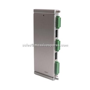
| Product Category | Dual Velocity Monitor — two-channel casing vibration monitor for the 3300 Machinery Protection System |
| Input Channels | Two independent velocity channels (Channel A and Channel B), each with its own full-scale range option |
| Compatible Transducers | Velomitor, High Temperature Velomitor System (HTVS), Velocity Seismoprobe — selectable by transducer-type option code |
| Transducer Type Options | 01 = 9200 / 74712 Seismoprobe, 500 mV/in/s, 2-wire, 10 kΩ input impedance; 02 = 47633 / 86205, 500 mV/in/s, 2-wire, 24.9 kΩ; 03 = 145 mV/in/s (CEC 4-126); 04 = Velomitor, 100 mV/in/s; 05 = HTVS, 145 mV/in/s |
| Sensitivity | 500 mV/in/s, 145 mV/in/s or 100 mV/in/s — jumper programmable on the module |
| Transducer Power Note | Transducer voltage must be selected for 24 VDC in the rack power supply when the Velomitor or HTVS option is used |
| Frequency Response (unfiltered) | Velocity Seismoprobe: 3–10,000 Hz (180–600,000 cpm) at −3 dB nominal; HTVS and Velomitor: 3–3,000 Hz (180–180,000 cpm) at −3 dB nominal |
| High-Pass Filter | Selectable across the range 3–400 Hz (180–24,000 cpm); 2-pole, 40 dB per decade (12 dB per octave) |
| Low-Pass Filter | Selectable across the range 24–3,000 Hz (1,440–180,000 cpm); 2-pole, 40 dB per decade (12 dB per octave) |
| Accuracy | ±0.33 % of full scale typical, ±1 % maximum at +25 °C (excluding RMS circuitry, integration and filters); ±2 % maximum at 2× trip multiply; ±3 % maximum at 3× trip multiply |
| Recorder Output | User-programmable per channel: +4 to +20 mA, 0 to −10 VDC, or +1 to +5 VDC, proportional to programmed monitor full scale |
| Recorder Accuracy | ±0.7 % of signal at +4 to +20 mA with ±0.09 mA offset at +25 °C; recorder output short circuit does not affect monitor operation |
| Buffered Transducer Outputs | Front-panel coaxial connectors and rear terminal connections; jumper-programmable for filtered or unfiltered signal |
| Alarm Setpoints | Independently adjustable Alert and Danger levels, 0 to 100 % of full scale, per channel |
| Alarm Relay Options | Epoxy-sealed, hermetically sealed or quad relay assemblies selected by option code; one relay module required per 3300 system |
| Trip Multiply | Supported — setpoints multiplied (typically 2× or 3×) under rack command from the System Monitor |
| Front Panel Indication | 63-segment vertical bargraph per channel; OK (green) and Bypass (red) LEDs; flashing LED for error and status conditions |
| Power Consumption | Nominal 1.5 W from the 3300 rack backplane (some listings state higher typical draw — confirm against your rack power budget) |
| Operating Temperature | 0 °C to +65 °C (+32 °F to +149 °F); storage −40 °C to +85 °C |
| Relative Humidity | Up to 95 % non-condensing |
| Rack Space | One slot in the 3300 System rack; not hot-swappable — rack power must be removed before insertion or removal |
| Dimensions / Weight | Single-slot 3300 module; approximately 0.8–1.3 kg depending on relay and option configuration |
| Compliance | Designed for API 670 machinery protection duty as part of a configured 3300 system |
| Lifecycle Status | Obsolete — 3300 platform moved to spare-part support in 2009, repairs-only in 2011, classified obsolete March 2014 |
| Migration Path | Bently Nevada 3500 Series with the appropriate seismic/velocity monitor module is the manufacturer’s recommended destination |