
Description
Application Scenarios:
A 180 MW gas turbine at a cogeneration plant began drifting off its scheduled load during ramp changes. The governor would command a fuel valve position, the valve would move, and then — over the next few minutes — the actual position would wander far enough to trigger a load deviation alarm. Operators compensated by trimming manually; the plant engineer suspected the actuator, then the LVDT feedback, then the hydraulic supply. All three checked out.
The fault was in the driver. One of the actuator driver channels in the MicroNet chassis had degraded to the point where its current output no longer tracked its commanded value accurately across the full stroke — in-range at low demand, progressively off at high demand, which is exactly the signature a ramp exposes and a steady-state check hides. Because the module monitors its own output voltage and current and can disable individual drivers, the degradation was visible in diagnostics the whole time; nobody had looked, because the module had never thrown a hard fault.
Swapping in a verified 5464-211 restored tracking across the full range, and the commissioning step that made it quick is worth noting: the module requires no calibration. An actuator can be replaced with a like actuator with no module or software adjustment, because the scaling constants live in EEPROM on the card. The technician seated the module, confirmed the FAULT LED was dark, and the loop was back in automatic within the hour — no potentiometer tweaking, no trim routine, no outage extension.
This is the pattern across the installed base: the 5464-211 sits in the fuel and steam control path of turbines that were commissioned decades ago and are expected to run for decades more, and when it degrades, the symptom masquerades as a mechanical or hydraulic problem until someone reads the diagnostics.
Parameter:
| Main Parameters | Value/Description |
|---|---|
| Product Model | 5464-211 |
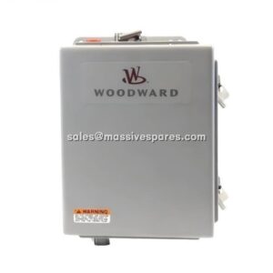
| Manufacturer | Woodward |
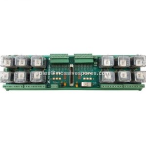
| Product Category | Integrating Actuator Driver module — MicroNet / NetCon 5000 control platform |
| Function | Converts CPU digital commands into proportional actuator-drive current for valve, rack and vane positioning |
| Output Signal Range | 0–25 mAdc or 0–200 mAdc, selectable by module variant — covers low-current and high-current actuator coils |
| Output Channels | Four proportional actuator-driver signals (MicroNet / NetCon 4-channel actuator architecture); confirm channel mapping against your chassis BOM |
| Resolution | 12 bits — fine enough to resolve small position increments without visible step in the actuator |
| Accuracy | 0.1 % of full scale at 25 °C — the figure that determines how closely actual valve position tracks commanded position |
| Temperature Drift | 150 ppm/°C — governs how much that accuracy degrades as cabinet temperature moves |
| Maximum Actuator Resistance | 45 Ω at 200 mA; 360 Ω at 25 mA — the load envelope the driver can push current through without saturating |
| Maximum Actuator Inductance | 1 H — sets the limit for large solenoid and servo-valve coils |
| Dither | Tunable amplitude, 25 Hz square wave — keeps hydraulic spools from stiction without showing up as position noise |
| Analog Driver Bandwidth | 50 Hz minimum — fast enough for governing loops, deliberately not faster |
| System Interface | Dual-port memory over the VME bus; output scheduling and scaling handled by onboard microcontroller |
| Calibration | Microcontroller-based using EEPROM-stored constants; no field calibration required, actuators replaceable like-for-like without adjustment |
| Diagnostics | Continuous per-channel voltage and current monitoring; individual driver disable on fault; load-fault, driver-fault, microcontroller watchdog and CPU-communication-loss detection; red FAULT LED |
| Redundancy | Operates within Triple Modular Redundant (TMR) MicroNet / NetCon 5000 architectures — the system continues running through a module fault |
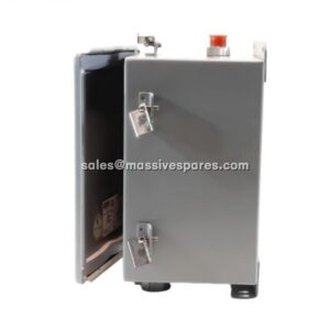
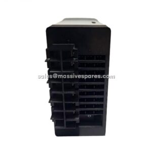
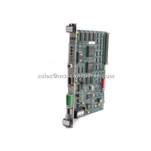
| Physical | Approx. 26 × 248 × 262 mm (2.6 × 24.8 × 26.2 cm), approx. 1.08 kg; chassis slot-mounted with two faceplate securing clips |
| Environment | Operating −20 °C to +55 °C (some listings cite wider); storage −40 °C to +105 °C; humidity up to 95 % non-condensing |
| Lifecycle Status | Obsolete — last-time-buy closed 31 July 2015; published Woodward repair window ended 2020; available from verified surplus, refurbished or repaired inventory only |
Technical Principles and Innovative Values:
Innovation Point 1 — The loop is closed at the driver, not just at the controller: many actuator interfaces simply convert a command into a current and hope. The 5464-211 writes output values into dual-port memory over the VME bus, then has its own microcontroller scale, schedule and continuously measure them. It monitors output voltage and current per channel and alerts the system to both channel faults and load faults, which means an opening coil, a rising resistance or a sticking spool is reported as an electrical signature before it becomes a position error.
Innovation Point 2 — Calibration that lives on the card: scaling constants are held in EEPROM and applied by the onboard microcontroller, so the 5464-211 requires no calibration and an actuator can be replaced with a like actuator with no module or software adjustment. For a plant, that eliminates an entire class of outage-extension risk — no trim pots to drift, no technician-dependent calibration ritual, no re-validation triggered by a like-for-like swap.
Innovation Point 3 — Fault containment at channel level: the system can individually disable the current drivers. A fault on one channel does not have to take down the other three, and in a TMR architecture the control function survives the event entirely. For a turbine, that is the difference between an alarm and a trip.
Innovation Point 4 — Dither as a designed feature: the 5464-211 provides a tunable-amplitude 25 Hz square-wave dither. Hydraulic servo valves and spools suffer from stiction — they stick, then jump. A small controlled dither keeps the spool in continuous micro-motion so it responds smoothly to small commands instead of in steps. Cheap drivers either omit dither or apply it fixed; having it tunable lets the loop be tuned to the specific actuator.
Innovation Point 5 — Bandwidth matched to the mechanics: with a 50 Hz minimum analog driver bandwidth and up to 1 H of actuator inductance supported, the 5464-211 is engineered to drive real valve coils, not laboratory loads. That is deliberately not a fast card — it is fast enough for governing while rejecting the electrical noise that a higher-bandwidth driver would amplify into position chatter.
Innovation Point 6 — Accuracy specified honestly: 0.1 % of full scale at 25 °C with 150 ppm/°C drift is a specification an engineer can design against. Combined with 12-bit resolution and defined actuator resistance limits (45 Ω at 200 mA, 360 Ω at 25 mA), it tells you in advance whether a given actuator will be driven accurately across its stroke — which is precisely the calculation that prevents the “actuator checks out but the loop still drifts” problem described above.