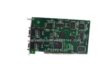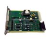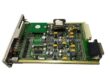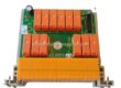
Description
The 5703-1 is Parker’s 5703/1 Setpoint Repeater Unit, a compact DIN-rail communications module from the Parker Eurotherm SSD drive accessories family. It was built for one job: let a reference DC590+ drive hand its 16-bit speed setpoint to a string of follower drives so the whole line stays in speed-lock, without installing a 5720 Quadraloc controller.
Electrically it is deliberately dumb — and that is the point. The 5703-1 is a pure electric-to-light converter. It takes the RS232-compatible signal that appears on the drive’s P3 port (the same port used offline for EEPROM upload and download), turns it into fibre-optic light for the next unit, and turns incoming light back into RS232 for its own drive. The module changes nothing in the signal; the drive firmware owns the scaling, the ratio math and the ramped demand. That separation is why the part has survived for decades in web lines where the only acceptable fault is no fault.
Application Scenarios
Picture a 60-metre paper or plastic-film line at 3 AM: unwind, pre-draw, coating station, chill roll, slitter and winder, each on its own DC590+ drive. The machine chief does not want five independent speed pots and a prayer. He wants the unwind to lead, the coat-roll to follow at a fixed ratio, and the winder to track without weaving. Copper RS232 between drives would be a noise antenna — 400 mm of it is the published maximum before transmission errors creep in — and a single comms fault means a web break, a washdown and a shift’s worth of scrap.
Instead, the P3 port of each drive plugs into a 5703-1 via the supplied 400 mm cable, and the units daisy-chain with plastic fibre. The reference drive’s scaled speed demand becomes an optical stream that cannot pick up motor noise, earth-loop offset or welder hash. A jumper on the 5703-1 decides whether the second transmitter repeats the incoming signal or echoes the outgoing one, so a single unit can feed two branches of the line — useful when the slitter and the winder sit on opposite sides of the machine. No Quadraloc, no new PLC motion program, no rewrite of the drive parameter set.
Parameter
| Main Parameters | Value / Description |
|---|---|
| Product Model | 5703-1 — Parker’s catalogue designation for the 5703/1 Setpoint Repeater Unit (SSD Link Hardware family) |
| Manufacturer | Parker Hannifin, Electrification Group — originally Parker SSD / Eurotherm Drives |
| Product Category | Drive communications module / setpoint repeater / fibre-optic converter (not a PLC CPU and not a safety device) |
| Primary Function | Repeats a 16-bit speed/setpoint word between DC590+ drives for speed-lock operation; the module itself does no scaling or arithmetic — that lives in the drive software |
| Host Interface | 1 × P3 port on the DC590+, RS232-compatible signal levels, 9-way D-type via the supplied 400 mm interconnect cable. P3 is otherwise the EEPROM service port, so confirm the port is configured for setpoint traffic before commissioning |
| Fibre Interface | 1 × fibre-optic receiver (fixed: accepts the signal from the preceding unit) plus 2 × fibre-optic transmitters. Plastic optical fibre is the intended medium; this is what gives the link its noise immunity and ground-loop freedom |
| Transmitter Jumper Logic | Jumper at the right-hand position (module mounted fibre-down) makes TX2 repeat the output signal; left-hand position makes TX2 repeat the input signal. The SK1-to-TX1 path is fixed and cannot be reconfigured — plan your branch topology around it |
| Default Point Map | Input side wired to “additional speed demand”, output side wired to “speed demand” in the drive block diagram; the 5703-1 can be re-pointed to other block-diagram parameters in the drive, so ratio, ramped and direct demands are all usable |
| Supported Modes | Direct, ratio and ramped speed-locking; accurate speed holding requires encoder feedback on the drives. It is not a high-accuracy synchroniser — that is the 5720 Quadraloc job, and the manual is explicit about the distinction |
| Supply Voltage | 21 to 26 VDC nominal for the 5703-2 sibling and the 5703 family; distributor listings for the -1 give an 18–30 VDC tolerance window. Fuse the supply and measure it with the load connected — a sagging 19 V rail is the usual cause of a “link present, speed dead” call |
| Current Consumption | Modest logic draw; published family figures sit well under 500 mA, with a 2.0 A / 2.5 A slow-blow fuse commonly specified on the 18–30 VDC builds. The module is not a power supply for the drives |
| Status Indication | Status output: 0 to 0.5 VDC = off; supply-rail voltage at up to 15 mA = on. A plain two-state health flag, not a diagnostic word — use it to drive a panel lamp or a digital input on the host |
| Connection Type | Screw terminals (0.2 to 2.5 mm²) plus the P3 plug cable; no field-configurable protocol or baud menu on the module itself |
| Mechanical | DIN-rail mounted box, standard 22 mm-wide footprint. Published dimensions vary by source and revision: ≈ 127 × 22 × 152 mm (5.0 × 0.9 × 6.0 in) is the consistent family figure; weight ≈ 100 g for the later 5703-2 form, ≈ 1.4 kg on older cased -1 listings — confirm the actual housing before ordering a panel cut |
| Environmental | 0 to +60 °C operating in the conservative spec, with the 5703-2 rated −10 to +60 °C and short-term storage to +90 °C; 10–90 % RH non-condensing; IP20 touch-protection only, so it lives inside the enclosure, not in the hose-down zone |
| Cable Guidance | Keep the copper P3 tail to 400 mm max; run the inter-unit distance on plastic fibre, not RS232. For very long or electrically hostile runs, an external converter can isolate the link and present RS485 to the line — a route Parker itself describes in the 590+ manual |
| Product Status | Obsolete / no longer an active OEM line item; supplied through verified surplus and test-to-print stock, with the P3 cable, jumper setting and fibre connectors matched to your revision |