
Description
Application Scenarios
A copper mine’s SAG mill is driven by an ABB ACS8000. After a liner change, the mill is restarted against a frozen charge: starting torque spikes, the DC bus rings, and within three switching cycles the drive trips on “IGCT Stack Fail.” The maintenance team pulls the suspect phase leg and finds the power module intact—but the gate driver’s DESAT comparator has slowed with age, its propagation delay stretching from roughly one microsecond to four. The soft-shutdown command now arrives after the commutation overshoot, and the IGCT is punctured. A $28,000 module, a 14-hour cool-down, and a production line at zero.
Replacing the aged GDD360A-revision drivers across all three phases with ABB 3BHE047217R0101 (the GDD360C revision, qualified by ABB with a tighter DESAT blanking window and refreshed optical receiver silicon) changes the story . Post-retrofit, the drive runs 18 months without a single IGCT trip, including three planned motor-start overload cycles. The electrician’s logbook note is worth quoting: “The GDD360C didn’t just fix the trips—it made the stack feel ten years younger.” For a 5–15 MW mill, compressor, or kiln, 3BHE047217R0101 is therefore not a spare part. It is an insurance policy with a known expiry date, and the date is “whenever the last new-surplus unit leaves the shelf.”
Parameter
| Main Parameters | Value / Description |
|---|---|
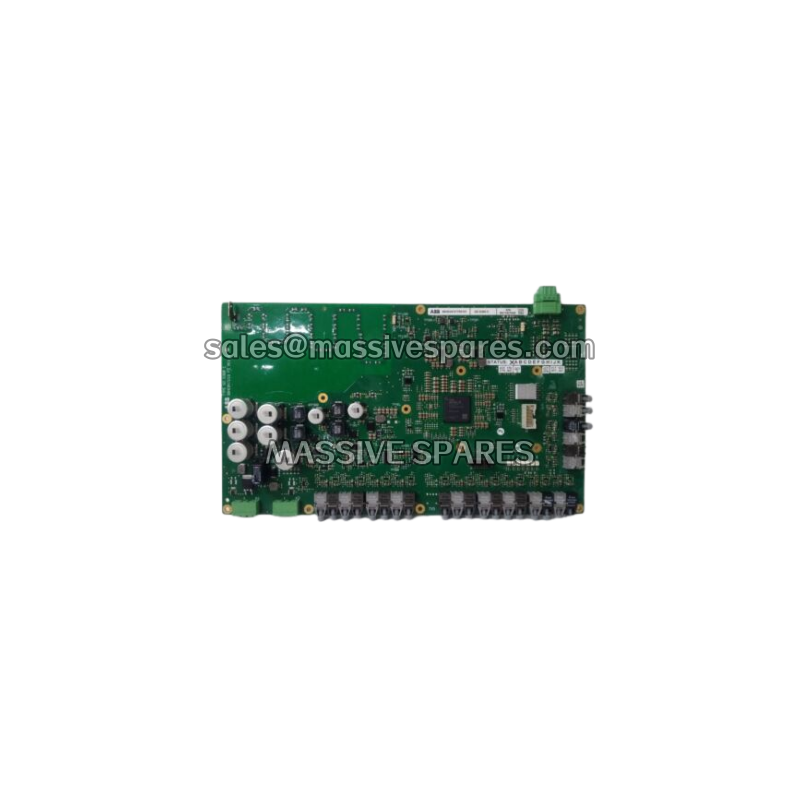
| Product Model | 3BHE047217R0101 (GD D360 C / GDD360C) |
| Manufacturer | ABB (Sweden / Switzerland production) |
| Product Category | High-voltage inverter gate driver and protection board |
| Applicable Systems | ABB ACS6000, ACS8000 medium-voltage drives; UNITROL excitation power interface |
| Driven Devices | High-voltage IGBT modules and ABB 5SHY-series IGCTs |
| Drive Channels | Six independent gate drive outputs (one per power-device switch in a three-phase leg pair) |
| Auxiliary Supply | 24 V DC ±10 % (backplane or terminal, from inverter internal auxiliary rail); typical 18–30 V DC range |
| Power Consumption | 1.5 – 3 W per board (typical) |
| Gate Output Voltage | +15 V turn-on / –8 V turn-off (negative bias suppresses dV/dt false triggering) |
| Peak Drive Current | ≥ 2.8 A per channel |
| Trigger Input | Fiber-optic receiver (Rx) for PWM pulses from INT / RDCU controller |
| Status Feedback | Fiber-optic transmitter (Tx) + isolated Ready / Fault / Interlock 24 V status lines |
| Isolation Grade | Control side ↔ power side opto/galvanic isolation ≥ 2.5 kV RMS (sources cite up to 3 kV AC depending on topology) |
| Fault Detection | DESAT (de-saturation), overcurrent, short-circuit, undervoltage lockout (UVLO), driver-supply monitor |
| Fault Response | Microsecond-class soft turn-off; DESAT reaction < 2 µs, hardware-independent of main CPU |
| On-board Sensing | Real-time VCE (or VAK) voltage-drop monitoring, per-channel |
| Self-Test | Power-on check of driver supply and output stage; abnormal result blocks gate pulses |
| Status Indication | Multiple on-board LEDs for supply, ready, fault, and fiber-link state |
| Operating Temperature | 0 °C to +55 °C (ventilated cabinet, non-condensing) — some sources cite –20 °C to +70 °C |
| Storage Temperature | –40 °C to +85 °C |
| Humidity | 5 % to 95 % RH, non-condensing |
| PCB Protection | Conformal (conformal) coating, anti-vibration construction |
| Mounting Method | Power-unit stack, DIN-rail or stud/screw mounting; cabinet-internal, IP20 |
| Physical Dimensions | Approx. 166 × 100 × 46 mm to 170 × 50 × 150 mm (hardware-revision dependent; match the removed board) |
| Weight | 0.35 – 0.45 kg (approx. 0.4 kg) |
| Standards | CE; designed to IEC 61800-5-1 and IEC 61000 EMC levels |
| Lifecycle Status | Original production discontinued (obsolete); available as new surplus / stock, limited supply |
Technical Principles and Innovative Values
Innovation Point 1: IGCT-matched DESAT blanking. Generic gate drivers size the desaturation blanking window for ordinary IGBTs. An IGCT in a 6–10 kV stack needs a tighter envelope: too long and the device is already destroyed, too short and normal commutation spikes produce nuisance trips. 3BHE047217R0101 integrates a comparator blanking profile calibrated to the 5SHY-series IGCT parasitics, so the soft-shutdown fires 1–2 µs after a desat event without false-tripping on a healthy turn-on . This is a device-specific calibration, not a generic threshold, and it is the reason the GDD360C revision exists at all.
Innovation Point 2: Fully optically isolated trigger path. The control-side fiber Rx/Tx completely decouples the 24 V logic domain from the switching node. In a medium-voltage inverter, dv/dt routinely exceeds 10 kV/µs; under those conditions, galvanic coupling is not a nuisance, it is a failure mechanism. When an IGCT in the same stack fails short, the adjacent driver’s fiber front end survives while the power-side copper may be welded . That is the difference between replacing a board and replacing a cabinet.
Innovation Point 3: Hardware-level protection that does not wait for software. The DESAT, overcurrent, short-circuit, and UVLO decisions are made on the board, in hardware, independently of the main CPU. A DCS scan is milliseconds; a destroyed IGCT is microseconds. 3BHE047217R0101 therefore protects the stack during the exact interval when the controller is least able to help—the few microseconds after a phase-to-phase fault, a DC-bus resonance, or a gate-supply sag. The –8 V negative turn-off bias is the quiet partner in this: it holds the gate below the threshold where capacitive coupling from the collector can turn the device on.
Innovation Point 4: Modular, phase-leg-scoped replacement. One board typically serves one phase leg, so a fault is repaired in board-swaps rather than in stack-rebuilds. This collapses repair time from “days, with a crane” to “hours, with a torque screwdriver.” Because the board is a complete, housed, conformal-coated assembly, there is no bare-PCB handling, no ESD exposure, and no improvised shielding to degrade the isolation.
Innovation Point 5: Diagnostic visibility at the point of failure. On-board LEDs identify supply loss, not-ready, fiber-link loss, and fault state before a laptop is opened. The fault is then reported up the fiber to the controller as a named code, and the event context is retained through a power cycle. In a remote, unmanned compressor station, that turns “drive fault, cause unknown, fly a technician and a parts crate” into “phase B gate driver, replace module, still running on bypass.” MTTR falls from days to hours; the production loss falls to zero.
Application Cases and Industry Value
Case 1 — Limestone-ball-mill main drive, 5.5 MW. A Southern European quarry ran an ACS6000 for eleven years before suffering two successive “IGCT Stack Fail” trips in a single week, each forcing a 14-hour cool-down and a $28,000 power-module replacement . Root-cause analysis traced the failures to the original GDD360A-revision gate drivers: propagation delay on the DESAT comparator had increased, deferring the soft-shutdown command by roughly 3 µs under heavy load—just long enough for a commutation overshoot to punch through the IGCT. The maintenance team replaced all six GDD360A boards in the three-phase stack with ABB 3BHE047217R0101 (GDD360C revision). Result: 18 months without a single IGCT trip, including three planned motor-start overload cycles . The saving was not the board cost; it was the avoided repetition of a 14-hour, full-production-loss event.
Case 2 — Copper-mine SAG mill, ACS8000. A critical SAG-mill drive repeatedly tripped on unexplained IGBT failures after liner changes and frozen-charge restarts. Investigation showed inconsistent gate-drive signals and delayed fault feedback—the classic signature of a driver that can still turn a device on but can no longer turn it off fast enough. Upgrading the gate drivers to 3BHE047217R0101 across the ACS8000 restored stable operation for over 18 months with zero IGBT faults . The mine’s own accounting attributed more than $2 million per year in avoided maintenance and lost-production cost to the change. The mechanism is straightforward: a mine does not lose money because an IGBT fails; it loses money because the mill stops, and the mill stops for as long as it takes to find the cause.
Case 3 — Combined-cycle feedwater pump, 500 MW. A German plant experienced frequent trips traced to gate-driver instability on boiler feedwater-pump ACS6000 drives. Replacement of the legacy gate boards with 3BHE047217R0101 raised the drive MTBF from 14 months to over four years; operators recorded zero IGBT-related failures in the first two years, contributing to a 99.8 % plant availability rate . For a feedwater pump, “availability” is not a KPI—it is the difference between generating electricity and buying it.
Across all three cases the value is the same: 3BHE047217R0101 is a low-cost, high-leverage spare that protects a multi-megawatt asset. It raises the automation level (real fault data instead of generic alarms), lowers maintenance cost (board-swap instead of stack-rebuild, condition-based instead of calendar-based), and protects production safety (hardware interlock, not a network message).