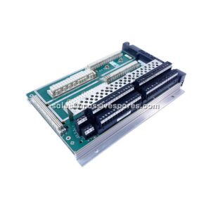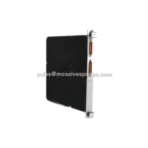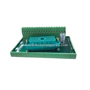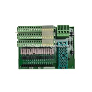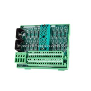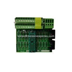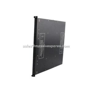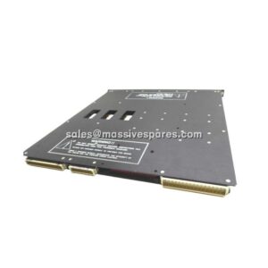

Description
Application Scenarios
Consider an LNG liquefaction train where the Tricon/Trident main processor chassis sits in a central safety cabinet, but the field-mounted shutdown valves, gas detectors, and compressor anti-surge I/O are distributed across three separate valve-control cabinets — 40 metres, 80 metres, and 150 metres away. The I/O bus cannot simply be run as one long daisy chain: signal integrity, termination, and power distribution must all remain within the TMR architecture’s strict fault-tolerance rules.
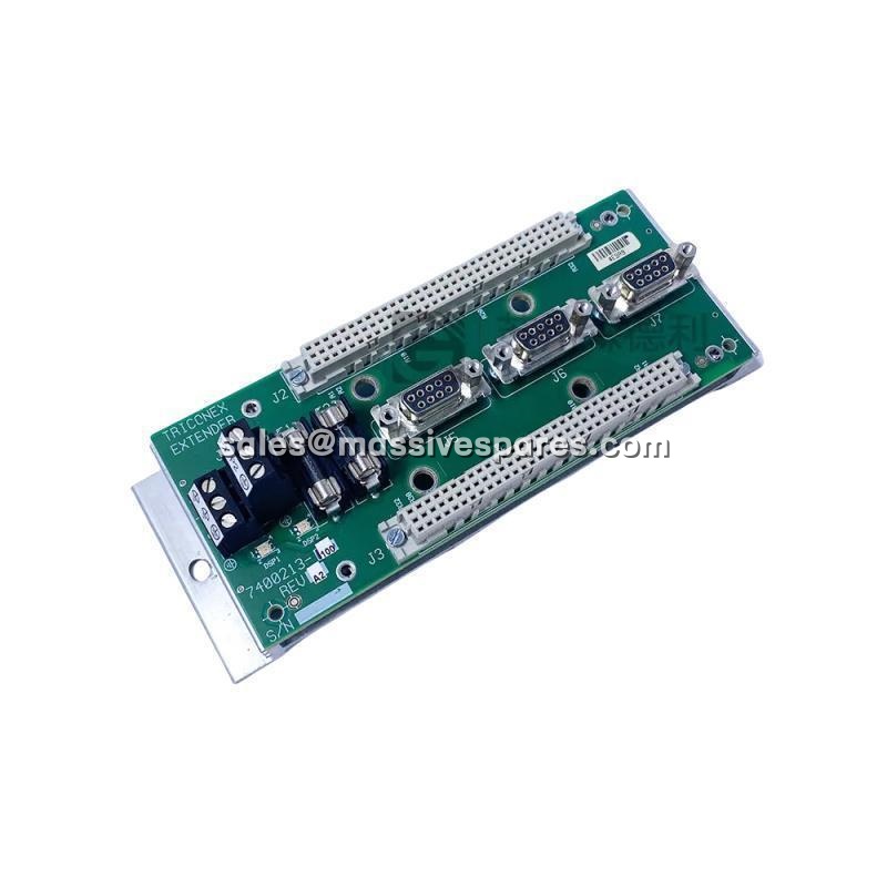
By installing a 7400213-100 at the top (or bottom) of each baseplate column, the engineering team gives every one of the three TMR channels its own 9-pin D-connector bus path to the next column. The extender routes the redundant bus signals cleanly across the full 200 m allowed I/O-bus length while distributing regulated 24 VDC logic power to the downstream modules. Bus termination is placed only at the baseplate farthest from the main processor — exactly where the Trident documentation requires it. The result: a distributed safety system that behaves electrically like a single chassis, with no single cable break capable of silencing more than one of the three redundant channels.
That is the unglamorous but vital job of the 7400213-100: it makes distributed structurally identical to local from the perspective of the safety logic.
Parameter
| Main Parameters | Value / Description |
|---|---|
| Product Model | 7400213-100 (also referenced as 7400213) |
| Manufacturer | TRICONEX (formerly Invensys; now Schneider Electric) |
| Product Category | Communication / I/O Extender Module (Baseplate Extender / Interconnect) |
| System Platform | Trident and Tricon TMR Safety Instrumented Systems |
| Core Function | Triple-channel TMR I/O-bus extension + configurable 24 VDC logic-power distribution to downstream baseplates |
| I/O Bus Architecture | Three fully independent TMR channels (Channel A / B / C) |
| Bus Paths | 3 channels, one dedicated cable per channel |
| Cable Interface | 9-pin D-connector (DB-9), one per channel |
| Installation Position | Top, bottom, or both ends of a baseplate column |
| Bus Termination | Required when total I/O-bus length exceeds 6 m (20 ft); terminate at baseplate farthest from MP |
| Maximum I/O Bus Length | 200 m (650 ft) including baseplates, extender modules, and extension cables |
| Logic Power Supply | 24 VDC ±10 % (configurable logic-power point; depends on whether column contains an MP baseplate) |
| Isolation | 2,000 Vrms typical channel / bus isolation |
| Mounting | Rack / baseplate mounted (keyed connector prevents misalignment); standard Trident extender slot |
| Hot-Swappable | Yes — supports online replacement in a powered TMR chassis |
| Operating Temperature | 0 °C to +60 °C (standard Trident range; some extender sources cite -20 °C to +70 °C) |
| Storage Temperature | -40 °C to +85 °C |
| Relative Humidity | 5 % to 95 % non-condensing |
| Vibration Resistance | 2 g peak, 5–200 Hz (per IEC 60068-2-6) |
| Shock Resistance | 15 g peak, 11 ms (per IEC 60068-2-27) |
| Safety Integrity Level | SIL 3 capable (IEC 61508 / IEC 61511) when configured in a certified TMR system |
| Dimensions (L × W × H) | Approx. 180 × 100 × 40 mm |
| Weight | Approx. 0.30–0.50 kg (module only) |
| Compliance | CE, UL; TÜV-certified SIL 3 in a Trident system |